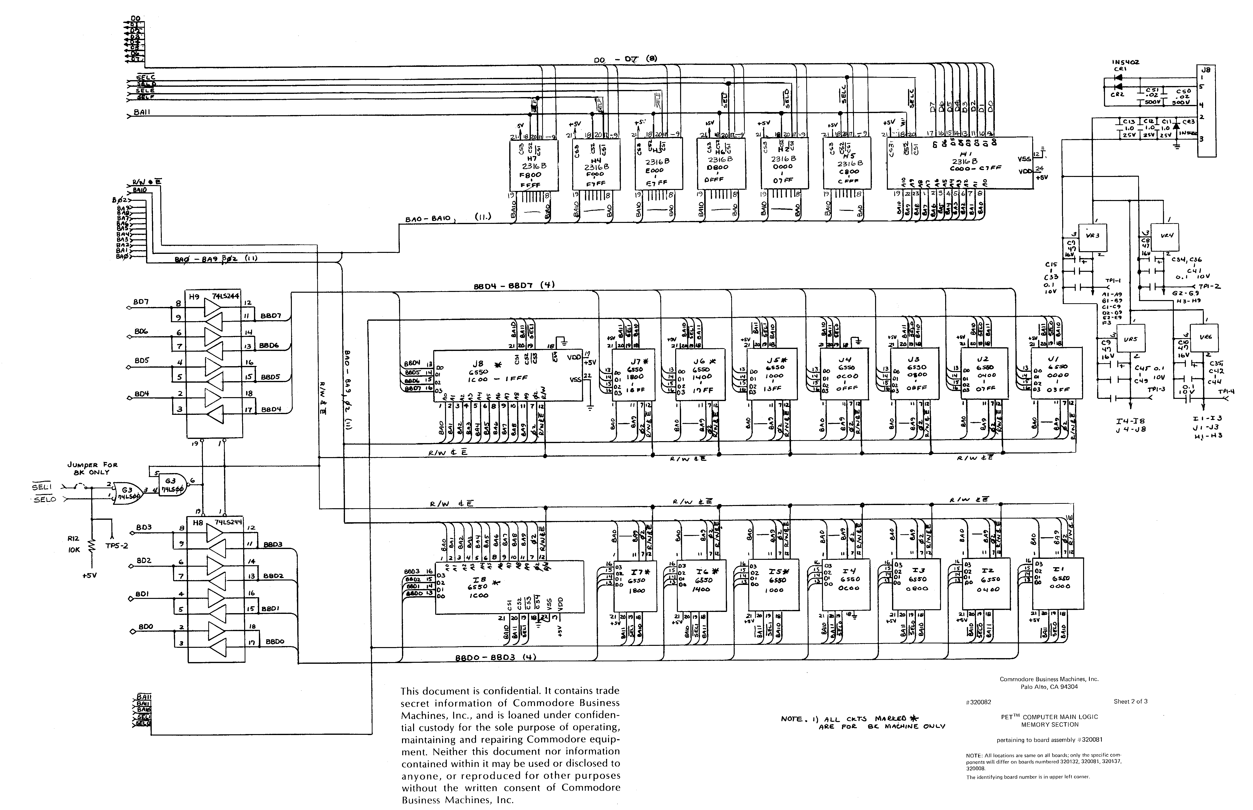
On Tue, Jul 28, 2009 at 6:29 AM, Philip Lord<random6000@mac.com> wrote:
> Hi everyone,
> I was hoping someone here would be able to help me. I hear you are a
> technical bunch.
>
> I have a dead PET 2001B (320081). When I first got it, it was blowing fuses

That could be bad/dried-out capacitors or a bad voltage regulator.

> I took the transformer are apart, and cleaned everything inside (lots of
> dust and grime), and re-assembled. Now It's not blowing fuses anymore (not
> sure why not), however the machine is still dead. The first thing I want to
> confirm what power is getting to the motherboard. I was wondering is anyone
> here knows both the AC voltages coming off the transformer (from memory I
> believe there are 5 tabs, not including the two lines from the mains power),
> and the voltages at the J8 power plug on the motherboard? I have looked on
> the net but have not been able to find this simple information. I think
> knowing these voltages would help me a lot.

I asked these questions last year when I was trying to get just a bare
board working.  I don't have the answers handy, but that vintage of
PET has several voltage regulators and several *independent* +5V
distribution sections.

<http://www.zimmers.net/anonftp/pub/cbm/schematics/computers/pet/2001/320081-2.gif>

> Also, with the power on I have measured the voltages on the motherboard
> across 5v line and GND, and it's measuring in the millivolt range...so thats
> not good.

You have to check in more than one place, but I'm certain that the
place you checked wasn't getting +5V when it should.

Essentially, I did up a spreadsheet last year (which is on a computer
that I can't access right now) that listed each section of the board
and what regulator powered it.  I did this because my board didn't
come with RAM or ROM plugged in - I was going to use a "Universal PET
RAM/ROM" board from Nicholas Welte
(http://freenet-homepage.de/x1541/hardware/petram.html), so I didn't
have to power any of the main RAM or the ROM sockets.  The schematic
referenced above has a note giving the layout (I did mine by hand)...

VR3 - A1-A9, B1-B9, C1-C9, D2-D9, E2-E9, F3
VR4 - G2-G9, H3-H9
VR5 - I4-I8, J4-J8
VR6 - I1-I3, J1-J3, H1-H3

So by function...

VR3 - Video, VLSI I/O, some random logic, and the CPU.
VR4 - Half the ROM sockets plus the bus buffers, keyboard decoder
('145) and some random logic.
VR5 - Half the SRAM sockets.
VR6 - The other half of the SRAM sockets plus the other half of the ROM sockets

I'm guessing there is a typo on the sheet, and that VR4 should be
H4-H9 and VR6 should be H1-H3, but that should be simple to verify one
way or the other.

You should check the output of each regulator to see that it's
producing voltage.  If you aren't getting anything out from any of
them, check the inputs.  A 7805 needs several volts to produce
regulated 5VDC.  Anything from about 7.5VDC in up to about 9VDC should
be fine (more works but just makes more heat).  If you have no input
voltage, check the large diodes CR1 and CR2.  Also check for shorts
between any power line (regulated or unregulated) and ground - you
could have a capacitor that is (was) shorting out.

Worst case, you could remove the regulators and provide a couple of
amps of externally regulated +5VDC, but this is a very simple power
supply to fix.  The exact input voltages aren't critical, but if the
7805s aren't getting ~8VDC, they won't put out +5VDC to feed
everything.

Good luck,

-ethan

       Message was sent through the cbm-hackers mailing list
Received on 2009-07-28 19:06:35
Archive generated by hypermail 2.2.0.